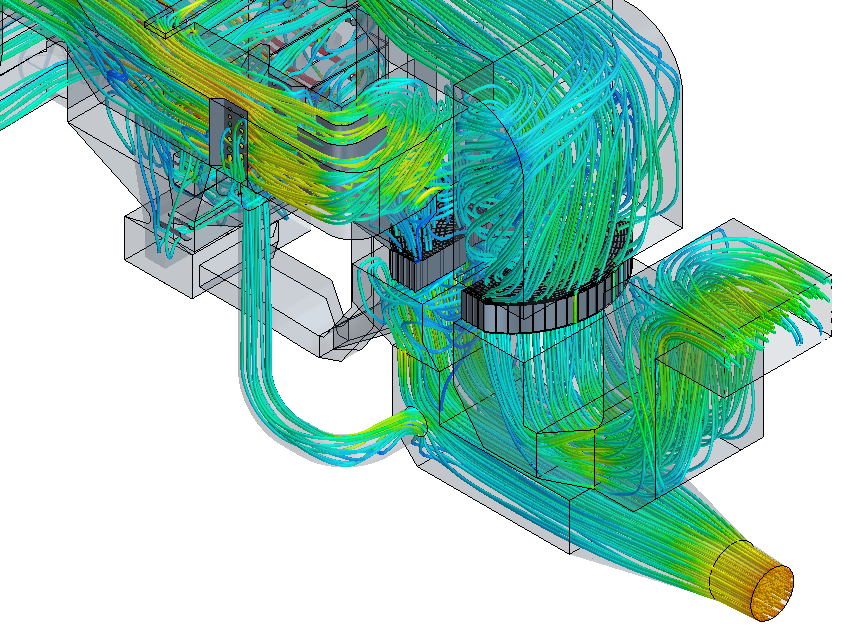
There is a constant need to improve the efficiency of power generating equipment, either to increase production or to decrease pollution. Most of the US’s power generating capacity was designed using technology that was over 10 years old and best practice design rules instead of explicit knowledge on the inner workings of the equipment. In the past few years, CFD has seen an explosion in use in the power generation industry because of the benefits that it provides. Some of these benefits include the ability to visualize flow at any point within the equipment, the ability to model the geometry at 1:1 scale instead of making scale model approximations and the ability to model reacting flows, which is typically not possible with scale models.
In one recently documented case, a coal fired plant was able to reduce NOx emissions by 35% at a cost of $4 per MW due to the insight they gained through CFD. Older plants have reported up to 75% NOx reduction without major equipment changes. Hydropower plants have been able to optimize their inlet plenums and turbine geometry to increase generating capacity and decrease operational costs. It is now standard procedure to implement CFD early in the design of wind farms to allow for optimal placement of the towers.
Equipment and processes that can be modeled with CFD include:
- Air heaters
- Ash formation and reduction
- Boilers and heat exchangers
- Burners
- Combustors
- Cooling towers
- Ducts
- Economizers
- Electrostatic precipitators
- Filters
- Fluidized beds
- Furnaces
- Hydropower
- Incinerators
- Manifolds
- Silencers
- Scrubbers
- Steam generators
- Turbomachinery
- Wind generation
- 316b compliance
- CAIR compliance


